Generated with AI4 min read
Francis Turbine
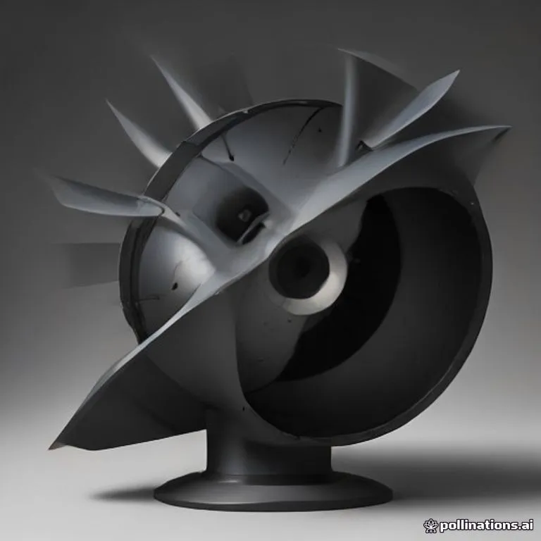
Brief description
A Francis turbine is a reaction water turbine that combines radial and axial flow concepts to extract energy from water under medium-to-high pressure heads. Water enters the turbine radially through a spiral casing (volute) and adjustable guide vanes, flows inward toward the center, and turns 90 degrees to discharge axially through a central draft tube. It is the most widely used water turbine in the world for large-scale hydroelectric power generation due to its exceptionally high efficiency (over 90%).
Use / Function
- Primary use: Generating continuous medium-to-large scale hydroelectric power from rivers and dam reservoirs.
- Secondary uses: Direct mechanical power for industrial complexes, water pumping operations, and energy storage in pumped-storage hydroelectric plants.
- Scale: Medium industrial plants (hundreds of kilowatts) to mega-hydroelectric dams (hundreds of megawatts), working efficiently under water heads ranging from 10 to 600 meters.
Operating principle
Reaction Force and Energy Conversion:
- Spiral Casing (Volute): Pressurized water from the penstock enters a decreasing spiral casing that maintains constant water velocity and distributes the flow evenly around the outer circumference.
- Wicket Gates (Stay Vanes & Guide Vanes): Water passes through stationary stay vanes and adjustable wicket gates, which direct the fluid at an optimal angle onto the runner blades while controlling total water flow.
- Inward Radial Flow: As pressurized water moves inward through the curved runner blades, its static pressure drops and it imparts momentum to the runner via reaction forces.
- Axial Turn & Exit: The water is turned 90 degrees from radial to axial direction as it exits through the bottom of the runner.
- Draft Tube Pressure Recovery: The exiting water flows down a expanding tube (draft tube) beneath the turbine, which decelerates the water and recovers kinetic energy by creating a suction pressure head below the runner.
How to create it
1. Runner and Blade Fabrication
- Cast or weld curved hydrofoil blades made from Steel or Bronze to withstand hydrodynamic forces and cavitation.
- Secure the blades between a solid top crown and bottom band to form the central reaction runner.
- Balance the runner dynamically on a heavy steel shaft supported by lubricated bearings.
2. Guide Mechanism and Spiral Volute Assembly
- Construct a spiral casing (volute) out of Cast Iron or welded steel plates.
- Mount a ring of pivoting guide vanes (wicket gates) around the inner circumference of the casing, linked to a central control ring to adjust gate angles.
3. Draft Tube and Discharge Channel
- Install an expanding conical draft tube directly beneath the runner outlet, extending below the tailrace water level.
- Mount the turbine assembly inside a reinforced structure above the tailrace discharge channel.
Materials needed
- Runner & Blades: High-strength Steel or corrosion-resistant Bronze.
- Housing & Casing: Cast Iron or thick structural steel plate.
- Working Fluid: High-pressure Water supplied via a penstock pipe from a dam or elevated reservoir.
Variants and improvements
- Pumped-Storage Reversible Francis Turbine: Operates as a turbine-generator in peak power demand hours, and reverses direction as a motor-pump during off-peak hours to pump water back into an upper reservoir.
- Variable-Speed Francis Turbine: Utilizes electronic power converters to maintain optimal efficiency across wide variations in reservoir head levels.
- Micro-Francis Turbine: Compact cast-iron or stainless steel units engineered for small community micro-hydro projects.
Limits and risks
- Cavitation: Localized low pressure at the exit of runner blades can form vapor bubbles that collapse violently, pitting metal surfaces and destroying blades over time.
- Silt Erosion: High-velocity water containing sand or abrasive sediment causes severe wear on runner blades and wicket gate seals.
- Complex Fabrication: Precise blade curvature and tight mechanical tolerances make manufacturing significantly more complex than simple impulse wheels.