Generated with AI3 min read
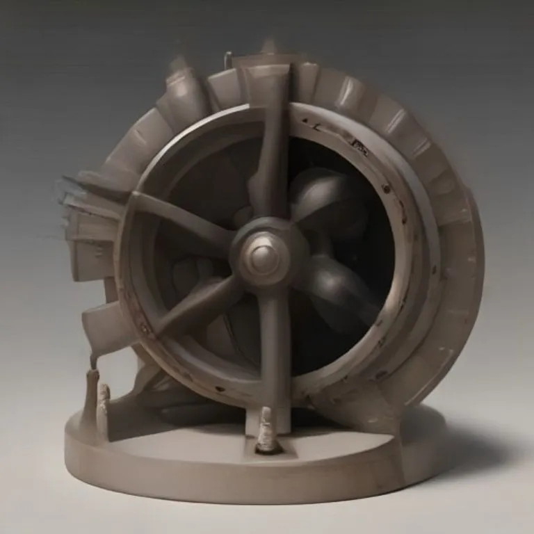
Centrifugal Pump
Brief description
A dynamic turbomachine that uses a rotating impeller to accelerate liquids radially outward, converting rotational kinetic energy into fluid pressure and continuous flow.
Use / Function
- Primary use: High-volume transfer of water and liquids for irrigation, municipal water distribution, drainage, and engine cooling systems.
- Secondary uses: Chemical process fluid circulation, mine dewatering, and sewage handling.
- Scale: Domestic / Agricultural / Industrial.
Operating principle
The centrifugal pump relies on hydrodynamic acceleration and momentum transfer:
- Fluid Entry (Eye): Liquid enters the central inlet (“eye”) of a rapidly rotating wheel fitted with curved blades (the impeller).
- Centrifugal Acceleration: As the impeller rotates, its blades fling the liquid outward toward the outer perimeter via centrifugal force, greatly increasing the liquid’s velocity and kinetic energy.
- Volute Conversion: The liquid exits the impeller tips into a expanding spiral casing (volute), where its high velocity is gradually slowed down, converting kinetic energy into static fluid pressure.
- Continuous Discharge: High-pressure fluid is forced out through the discharge outlet while creating a low-pressure zone at the impeller eye that continuously draws in fresh fluid.
How to create it
Minimum functional version
- Casing Fabrication: Cast or weld a two-part spiral volute housing made of Cast Iron or heavy Steel with a central axial inlet and tangential outlet.
- Impeller Construction: Fabricate a rotating disc with curved backward-swept vanes mounted on a central drive shaft.
- Shaft & Bearings: Mount the shaft through a sealed bearing housing in the rear casing wall using packed grease glands to prevent leaks.
- Assembly: Precision-mount the impeller inside the volute with minimal clearance between the blade edges and casing walls.
- Coupling: Connect the drive shaft to a motor, steam engine shaft, or belt pulley.
Technical level
Intermediate to Advanced. Requires precise dynamic balancing of the impeller and effective shaft seals to prevent fluid leakage.
Materials needed
- Essential materials:
- Tools:
- Lathe, foundry equipment or welding rig, drill press, dynamic balance jig.
Variants and improvements
- Multi-Stage Centrifugal Pump: Arranges multiple impellers in series on a single shaft to achieve high head pressures for deep wells or steam boiler feed pumps.
- Axial-Flow (Propeller) Pump: Uses a propeller-shaped rotor for ultra-high discharge rates at low pressure heads.
- Self-Priming Pump: Features an integral reservoir to purge air pockets automatically during startup.
Limits and risks
- Cavitation: Operating under low intake pressure creates vapor bubbles that collapse violently on impeller surfaces, causing rapid pitting and failure.
- Priming Requirement: Standard centrifugal pumps cannot pump gas or self-prime; the casing must be filled with liquid before starting.
- Dry Running: Running the pump empty destroys shaft seals and bushings due to friction heating.