Generated with AI4 min read
Pelton Wheel
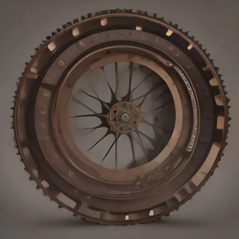
Brief description
The Pelton wheel is an impulse-type water turbine designed to extract mechanical energy from high-velocity water jets. It is uniquely efficient for high hydraulic heads (vertical water drop heights) and low flow rates, making it one of the most practical and high-performing devices for generating electricity in remote or mountainous environments.
Use / Function
- Power Generation: Driving Electric Generators to produce electricity at high efficiency.
- Direct Mechanical Work: Powering mills, water pumps, or saws directly via mechanical shafts.
- Scale: High-performing at local, regional, or industrial scales, particularly in mountainous regions with high elevation drops.
Operating principle
The Pelton wheel exploits the kinetic energy of a high-pressure, high-velocity water jet:
- Velocity Conversion: Water from a high elevation source is directed through a narrowing nozzle, converting pressure into a high-speed jet of water.
- Symmetrical Splitting: The jet hits the center of the double-cup-shaped buckets attached to the wheel’s rim. Each bucket features a central ridge (splitter) that divides the water stream into two equal parts.
- Momentum Transfer: The split streams are redirected backward, almost 180 degrees, transferring nearly all of their kinetic energy to the bucket.
- Rotation: This immense force drives the wheel to rotate at high speeds, turning the central shaft.
How to create it
1. The Runner and Buckets
- Cast or forge double-cup-shaped buckets (splitter in the center) from Iron or Steel. The double-cup design is critical; flat blades or single cups lose more than half of the potential efficiency.
- Bolt or weld the buckets securely around the outer rim of a heavy metal disk (the runner).
2. Shaft and Mounting
- Mount the runner onto a strong, balanced Steel shaft.
- Support the shaft with heavy-duty Bearings to minimize friction and handle radial loads.
3. Nozzle System
- Build a tapered nozzle at the end of a high-pressure pipe (penstock).
- Install a needle valve inside the nozzle to regulate the water jet’s diameter and speed without losing velocity.
4. Directing and Housing
- Align the nozzle so the jet strikes the splitters of the buckets perpendicularly at the wheel’s tangent.
- Enclose the entire assembly in a steel or concrete housing to prevent water splashing and direct the exhausted water downward.
Materials needed
- Buckets & Runner: Steel or Iron (cast bronze can also be used for corrosion resistance).
- Shaft: Heavy-duty carbon Steel.
- Nozzle: Machined brass, bronze, or steel.
- Bearings: Precision steel rolling-element bearings.
- Housing: Steel sheets, timber, or Concrete.
Variants and improvements
- Multi-Nozzle Pelton: Placing multiple nozzles around the wheel increases the power output without needing a larger runner.
- Turgo Turbine: A modification where the jet strikes the wheel at an angle, allowing smaller wheels to handle higher flow rates.
- Micro-Hydro Pelton: Compact, pre-assembled packages that can be dropped into mountain streams to provide immediate off-grid power.
Limits and risks
- High Head Dependency: Extremely inefficient at low hydraulic heads (low drop height), where reaction turbines like the Kaplan or Francis are superior.
- Nozzle Clogging: Any debris, sand, or leaves in the water can clog or erode the nozzle, requiring a filtration/settling basin before the intake.
- Speed Overshoot: If the electrical load is suddenly disconnected, the turbine can spin out of control (runaway speed), potentially tearing itself apart due to centrifugal forces. A mechanical governor or deflector is required for safety.
Related inventions
- Water Turbine: The general family of water-driven rotary machines.
- Electric Generator: The primary load connected to the Pelton wheel’s shaft.
- Water Wheel: The low-speed, gravity-driven ancestor.
- Bearings: Essential for maintaining high-speed rotation.