Generated with AI5 min read
Spark-Gap Transmitter
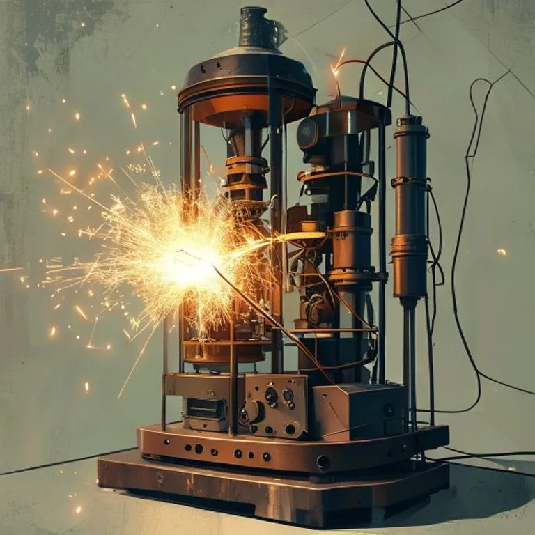
Brief description
A spark-gap transmitter is the earliest type of radio transmitter, capable of generating radio frequency electromagnetic waves by creating an electrical spark across a gap. Combined with a simple receiver (such as a coherer), it allowed the transmission of the first wireless signals, laying the foundation for all modern telecommunications.
Use / Function
- Wireless Telegraphy: Sending messages over long distances without physical wires using Morse code.
- Maritime Communication: Allowed ships at sea to communicate with land and other vessels (especially critical for SOS emergency distress calls).
- Scale: Regional/long-distance (can span hundreds or even thousands of kilometers with high-voltage power sources and large antennas).
Operating principle
A spark-gap transmitter converts direct current (DC) electrical energy into high-frequency electromagnetic radiation (radio waves):
- Power Supply and Charging: A low-voltage power source, such as a Battery, supplies electricity to an induction coil. The coil acts as a step-up transformer, converting low-voltage DC into high-voltage alternating current (AC).
- Capacitive Storage: This high-voltage charge is stored in a capacitor, such as a Leyden Jar (made of glass and metal).
- The Spark: Once the voltage across the capacitor reaches a high enough threshold, it breaks down the air resistance in a narrow gap (the spark gap), creating an electrical spark.
- Resonant Oscillation: When the spark fires, the stored energy in the capacitor rushes across the spark gap and through a tuning coil made of heavy Copper wire. The capacitor and coil form a resonant LC circuit, causing the electricity to rapidly oscillate back and forth at a specific radio frequency.
- Radiation: This high-frequency oscillating current is fed to a large wire antenna and ground system, radiating into space as an electromagnetic wave (a “damped wave”).
How to create it
1. Constructing the Spark Gap
- Fix two brass or Copper bolts or thick wires to an insulating base made of dry Wood or plastic.
- Position the bolts so their tips face each other, separated by a tiny adjustable gap of approximately 1 to 3 millimeters.
2. Preparing the Induction Coil
- Create an induction coil (or Ruhmkorff coil) to step up the voltage.
- Wind a primary coil of thick Wire around an iron core, and wind a secondary coil consisting of thousands of turns of very fine insulated wire over the primary. Use an automatic interrupter switch (buzzer mechanism) to rapidly connect and break the primary circuit to generate high-voltage pulses in the secondary.
3. Adding a Resonant Capacitor
- Construct a simple high-voltage capacitor. A Leyden jar made from a Glass jar lined inside and out with metal foil is ideal.
- Connect this capacitor in parallel with the secondary terminals of the induction coil and the spark gap.
4. Winding the Tuning Coil (Helix)
- Wind 10 to 20 turns of heavy copper wire around a wooden frame to form an antenna tuning coil.
- Connect this coil in series with the spark gap, an elevated antenna wire (stretched long and high), and a good electrical connection to the earth (ground).
5. Operation
- Connect a telegraph key in series with the battery and the primary coil.
- Pressing the key closes the circuit, generating sparks across the gap and sending out bursts of radio waves corresponding to Morse code signals.
Materials needed
- Induction Coil: To generate high voltages. Sourced from Wire and Copper.
- Telegraph Key: A simple spring-loaded switch. Sourced from Metal and Wood.
- Battery: Direct current power source. Sourced from Battery.
- Leyden Jar: High-voltage capacitor. Sourced from Glass and metal foil.
- Spark Gap: Two adjustable metal rods or bolts. Sourced from Copper or Brass.
- Antenna Wire: Long conductive wire to radiate the signal. Sourced from Wire.
Variants and improvements
- Rotary Spark Gap: Instead of two fixed electrodes, a spinning metal wheel with electrodes is used. This creates a rapid, high-pitched musical spark tone, which is much easier for operators to hear through background static.
- Quenched Spark Gap: Using a series of multiple small spark gaps in airtight chambers. This extinguishes the spark extremely quickly, preventing energy from being wasted back into the transmitter circuit and creating a cleaner, more efficient signal.
Limits and risks
- Broadband Interference: Spark-gap transmitters generate “dirty” signals that splash across a very wide range of radio frequencies (electromagnetic noise). Because of this, they quickly jam other nearby radio communications and are globally banned under modern spectrum regulations.
- Lethal Voltages: The induction coils generate thousands of volts of electricity. Touching the high-voltage side of the transmitter during operation can cause a fatal electric shock.
- Ozone and Fire Hazards: The continuous electrical spark generates ozone, nitrogen oxides, and heat, presenting a localized respiratory hazard and a potential fire risk if flammable materials are nearby.