Generated with AI3 min read
Oscilloscope
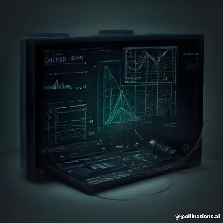
Brief description
An oscilloscope is an electronic test instrument that graphically displays varying signal voltages over time as a two-dimensional plot. It is the single most essential diagnostic tool for analyzing, troubleshooting, and rebuilding electrical and electronic circuits.
Use / Function
- Waveform Analysis: Measures voltage amplitude, frequency, phase shift, and signal distortion.
- Circuit Troubleshooting: Identifies faults, ripple in power supplies, and noise in communication channels.
- Timing Measurement: Determines pulse width, rise time, and signal delays in logic or radio circuits.
- Transducer Testing: Visualizes acoustic, mechanical, or optical sensor signals converted into electrical voltage.
Operating principle
- Signal Conditioning: An incoming electrical signal passes through an attenuator and amplifier to scale the vertical axis (Y-axis voltage).
- Time Base Generation: A sawtooth wave generator creates a linear sweep voltage across the horizontal axis (X-axis time), driving the electron beam from left to right across the screen repeatedly.
- Beam Steering: Amplified vertical and horizontal voltages are applied to deflection plates inside a Cathode Ray Tube.
- Visual Trace: The electron beam traces a continuous graph of voltage versus time on the luminescent screen.
How to create it
- Build the Display Unit: Fabricate or obtain a Cathode Ray Tube with electrostatic deflection plates and high-voltage power supply.
- Design the Vertical Amplifier: Assemble a wideband amplifier circuit using Vacuum Tube or Transistor components to amplify weak signals without distortion.
- Construct the Time Base Generator: Build a relaxation oscillator or sawtooth circuit (using capacitors and switches) to produce a linear horizontal sweep.
- Implement Triggering Circuitry: Add a comparator circuit to synchronize the time base sweep with the incoming signal, stabilizing the displayed trace.
- Calibrate and Enclose: Calibrate screen grid graticules with known voltage and frequency references, then house inside a shielded Steel chassis.
Materials needed
- Display: Cathode Ray Tube with high-voltage supply.
- Conductors & Coils: Copper Wire and shielded coaxial cables.
- Components: Resistor, Capacitor, and Vacuum Tube or Transistor arrays.
- Chassis: Enclosed metal frame of Steel or Aluminum for electromagnetic shielding.
Variants and improvements
- Analog Storage Oscilloscope: Holds traces on screen for single-shot transient events.
- Dual-Beam / Dual-Trace Oscilloscope: Compares two distinct input signals simultaneously.
- Digital Storage Oscilloscope (DSO): Digitizes signals using analog-to-digital converters and stores waveforms in memory.
- Vector Scope: Displays phase relationships between audio or video channels.
Limits and risks
- Bandwidth Limitations: High-frequency signals require advanced amplifier response and high CRT writing speeds.
- High Voltage Danger: Anode voltages inside the CRT display reach thousands of volts.
- Probe Loading: Improper measurement probes can distort sensitive high-impedance test circuits.