Generated with AI
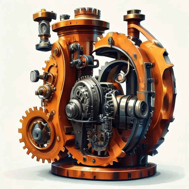
Gear Pump
Made of
Brief description
A Gear Pump is a type of positive displacement pump that uses the meshing of gears to pump fluid by displacement. It is robust, simple, and capable of pumping high viscosity fluids with great efficiency. It is fundamental in hydraulic and lubrication systems.
Use / Function
- Pumping viscous fluids: Ideal for oils, fuels, paints, and resins that would be difficult for other pumps.
- Lubrication systems: Provides a constant flow of oil to heavy machinery, such as Rolling Mills and engines.
- Hydraulic power: Generates pressure for hydraulic cylinders and motors in machinery.
- Fuel transfer: Commonly used in oil burners and fuel systems.
Operating principle
The pump works on the principle of positive displacement. It consists of two gears (driver and idler) enclosed in a tight-fitting casing.
- As the gears rotate, the teeth separate on the inlet side, creating a partial vacuum that draws in fluid.
- The fluid is trapped in the spaces between the teeth and the casing wall.
- The fluid is carried around the casing to the outlet side.
- On the outlet side, the gear teeth mesh again, forcing the fluid out under pressure. The central mesh acts as a seal preventing fluid from flowing back.
How to create it
- Housing: Fabricate a sturdy casing (usually cast metal) with an “8” shaped cavity to house the two gears with minimal clearance. It must have inlet and outlet ports.
- Gears: Machine two identical Gears (usually spur or helical). Precision is key; the fit with the casing must be nearly perfect to prevent internal leakage.
- Shafts and Bearings: Mount the gears on shafts supported by Bearings or bushings. One shaft protrudes to connect to the power source.
- Sealing: Install seals on the shafts to prevent fluid leakage to the outside.
- Assembly: Place the gears in the housing, secure the cover, and connect the drive shaft to a motor or crank.
Materials needed
- Gears and Shafts: Hardened Steel or Bronze to resist wear and fatigue.
- Housing: Cast Iron, steel, or aluminum. It must be rigid to not deform under pressure.
- Seals: Treated leather, rubber, or fiber gaskets.
- Lubricant: The pumped fluid itself usually lubricates the gears and bearings.
Variants and improvements
- External gear pump: The classic configuration with two gears side-by-side.
- Internal gear pump: A smaller gear rotates inside a larger one with internal teeth. It is more compact and quieter.
- Helical gears: Using angled teeth reduces noise and provides smoother flow, although it generates axial thrust.
- Lobe pump: Similar to a gear pump but the lobes do not touch (synchronized by external gears), allowing pumping of fluids with solids or shear-sensitive fluids.
Limits and risks
- Suspended solids: Does not tolerate solid or abrasive particles well, which can scratch gears and housing, quickly reducing efficiency.
- Fit and Tolerances: Requires high precision manufacturing. If the gap between gears and housing is large, fluid will leak internally (slip), reducing pressure.
- Excessive pressure: If the outlet is blocked, pressure can rise until destroying the pump or pipes. A safety relief Valve is required.
- Cavitation: If the inlet is restricted or speed is excessive, vacuum bubbles can form and implode, damaging internal components.