Generated with AI3 min read
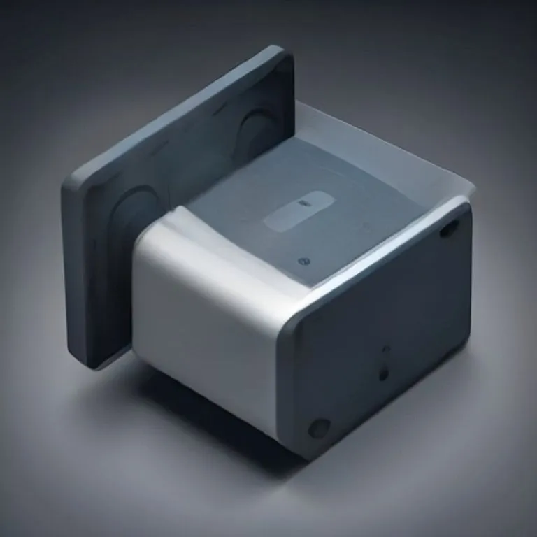
Thermoelectric Generator
Made of
Brief description
A thermoelectric generator (TEG) is a solid-state device that converts temperature differences directly into electrical energy using the Seebeck effect. By joining two dissimilar electrical conductors or semiconductors across a thermal gradient, continuous electric current is generated without any moving mechanical parts.
Use / Function
- Waste Heat Harvesting: Capturing waste heat from exhaust pipes, chimneys, stoves, and industrial kilns to produce electricity.
- Remote Power Supply: Powering radios, sensors, or low-voltage lighting using the heat of a simple wood stove or kerosene lamp.
- Off-Grid Energy: Reliable solid-state power source where mechanical generators are impractical or too loud.
- Scale: Portable micro-generators (milliwatts to watts) to industrial heat recovery arrays (hundreds of watts).
Operating principle
- Seebeck Effect: When two different conductors (such as iron and constantan, or bismuth telluride semiconductor pairs) are joined at two junctions held at different temperatures, an electromotive force (voltage) develops.
- Thermal Gradient: Heat flows from the hot junction (stove, exhaust) to the cold junction (heat sink, cooling fins).
- Electron Flow: Heat energy causes charge carriers (electrons or holes) to diffuse from the hot side to the cold side, producing electric current.
- Series Connection: Connecting dozens of thermocouples in electrical series and thermal parallel increases output voltage to usable levels (e.g. 5V–12V DC).
How to create it
- Thermocouple Junctions: Wire together alternating pairs of dissimilar metals (e.g., Copper and iron/constantan Wire) by twisting and soldering or welding joint pairs.
- Thermopile Assembly: Arrange the hot junctions together on one flat thermally conductive plate and cold junctions on an opposing plate.
- Heat Sink Attachment: Attach metal cooling fins or water cooling blocks to the cold plate to maximize the temperature difference.
- Insulation: Place thermal insulation around individual wire legs between hot and cold sides to prevent direct heat leakage.
- Electrical Connection: Wire the thermopile leads to a boost converter or voltage regulator to power devices or charge batteries.
Materials needed
- Conductors: Dissimilar metal Wire pairs (such as Copper and nickel/iron alloys) or semiconductor thermoelectric modules (P-N pairs).
- Heat Plates: Flat Metal plates (aluminum or copper) for thermal conduction.
- Heat Sinks: Metal fins or radiator blocks for heat dissipation on the cold side.
- Insulation: Ceramic paper or mineral insulation to prevent heat transfer between plates.
Variants and improvements
- Stove-Top TEG: Placed directly on top of wood stoves to power circulation fans or charge small battery banks.
- Radioisotope Thermoelectric Generator (RTG): Uses decay heat from radioisotopes to power deep space probes for decades.
- Semiconductor Thermopiles: Bismuth-telluride-based modules providing higher efficiency (5%–10%) than simple metal thermocouples.
Limits and risks
- Low Efficiency: Typical energy conversion efficiency is only 2% to 8%, requiring large heat differences to yield modest power.
- Overheating Risk: Excessively high temperatures can melt solder joints or degrade semiconductor material permanently.
- Cooling Requirement: Requires effective cold-side cooling (air fins or flowing water) to maintain the necessary temperature gradient.