Generated with AI
Connecting Rod
Made of
Brief description
A connecting rod (also called a conrod) is a rigid member that connects a piston to a crankshaft or a crank. It serves as the mechanical link that transmits force and motion between the two, enabling the conversion of reciprocating (linear) motion into rotating motion.
Use / Function
- Motion Conversion: Fundamental in internal combustion engines to turn the up-and-down motion of pistons into the rotation of the wheels.
- Pumps: Used in hand pumps and windmills to convert rotation into the linear pumping action.
- Steam Engines: Transfers power from the sliding piston to the drive wheels.
Operating principle
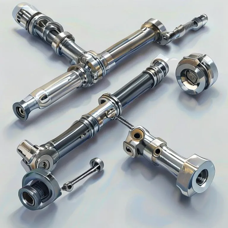
The connecting rod has two ends:
- Small End: Usually attached to a piston or a sliding crosshead via a pin.
- Big End: Attached to the crank pin of a crankshaft. As the piston moves linearly, the rod pushes or pulls the crank. Because the crank pin moves in a circle, the connecting rod must pivot at both ends, allowing it to translate the straight-line movement into a circular path.
How to create it
1. The Body
- Must be extremely strong to resist buckling under compression and breaking under tension.
- Usually has an “I-beam” cross-section to maximize strength while minimizing weight.
2. The Bearings
- Both ends must have smooth bearings to allow rotation around the pins.
- In primitive versions, these can be simple holes with heavy lubrication.
- In modern versions, they use precision bushings or split bearings.
3. Fastening
- The “Big End” is often split into two pieces (the rod and a cap) so it can be clamped around the crankshaft. These are held together by high-strength bolts.
Materials needed
- Structural: High-strength Iron or Steel. Cast iron is sometimes used for lower-stress applications.
- Bearings: Bronze, brass, or “Babbitt metal” (a soft alloy that reduces friction).
- Lubrication: Animal fat, grease, or motor oil is essential to prevent the rod from seizing.
Variants and improvements
- Master-and-Slave Rods: Used in radial engines (like those in early airplanes) where multiple rods connect to a single crank pin.
- Fork-and-Blade Rods: Used in V-engines to allow two cylinders to share the same longitudinal space on the crankshaft.
Limits and risks
- Fatigue: The rod is subjected to millions of cycles of stress. A small crack can lead to a “thrown rod,” which often destroys the entire engine.
- Weight: If the rod is too heavy, it creates vibration and limits the speed of the machine.
- Lubrication Failure: Without oil, the bearings will melt or seize, causing immediate mechanical failure.