Generated with AI3 min read
Bourdon Gauge
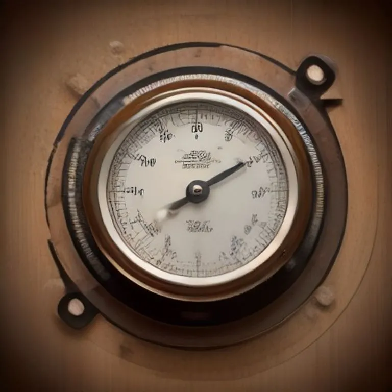
Brief description
A mechanical instrument designed to measure fluid or gas pressure using a flattened, curved C-shaped metal tube that tends to straighten when internal pressure increases.
Use / Function
- Primary use: Measuring and monitoring pressure in steam boilers, compressed gas systems, water mains, and industrial pressure vessels.
- Secondary uses: Vacuum measurement, hydraulic system monitoring, and engine manifold pressure indication.
- Scale: Workshop / Industrial / Power plant.
Operating principle
The Bourdon gauge operates on elastic tube deformation under internal fluid pressure:
- Curved Elastic Tube: A flattened elliptical tube made of flexible metal (such as brass or copper) is bent into a C-shape with one end fixed to the fluid inlet and the opposite end sealed and free to move.
- Pressure Expansion: As pressurized fluid enters the open inlet, the flattened cross-section of the tube attempts to regain a circular shape.
- Mechanical Uncoiling: This cross-sectional rounding creates stresses that force the overall C-shaped curve of the tube to straighten out.
- Linkage & Pointer: The slight movement of the sealed tip is amplified through a mechanical linkage and toothed sector gear, turning a pinion shaft attached to a pointer across a calibrated dial.
How to create it
Minimum functional version
- Tube Fabrication: Flatten a thin-walled Brass or Copper tube into a slightly elliptical cross-section and bend it smoothly into a C-shape arc.
- Sealing & Mounting: Solder one end of the C-tube rigidly into a brass inlet fitting, and solder a closed cap with an attachment eyelet onto the opposite free end.
- Linkage Assembly: Attach a short connecting rod from the free end eyelet to a pivoted lever fitted with a small gear sector.
- Indicator Dial: Mesh the gear sector with a small pinion gear bearing a central needle, and mount the assembly over a printed dial face behind a protective Glass lens.
- Calibration: Connect the gauge to a known pressure source (e.g., a water column or reference pump) and mark pressure increments on the dial face.
Technical level
Intermediate. Requires precise soldering, smooth gear linkage fabrication, and accurate pressure calibration.
Materials needed
- Essential materials:
- Tools:
- Soldering iron / blowtorch, wire cutters, fine file, pliers, calibrating pump.
Variants and improvements
- Spiral and Helical Tubes: Winding the tube into a multi-turn spiral increases tip displacement, providing greater pointer rotation without complex gears.
- Diaphragm Gauge: Uses a corrugated metal diaphragm for low-pressure gas or viscous liquid measurement.
- Differential Gauge: Incorporates two Bourdon tubes linked to a single pointer to indicate pressure differences between two lines.
Limits and risks
- Overpressure Damage: Exceeding the elastic limit of the tube causes permanent deformation, ruining calibration.
- Vibration Fatigue: High vibration can wear gear teeth or induce metal fatigue in the tube walls.
- Corrosive Fluids: Corrosive chemicals can erode the thin tube walls, leading to dangerous high-pressure leaks or bursts.