Generated with AI3 min read
Solenoid
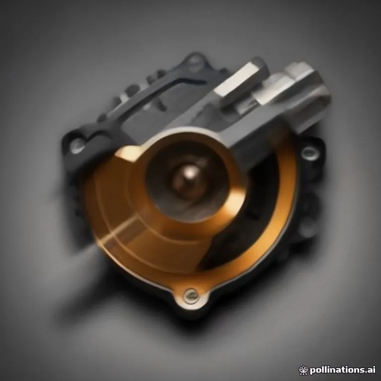
Brief description
A solenoid is an electromechanical device consisting of a cylindrical coil of insulated wire wrapped around a movable soft iron plunger or core. When energized with an electric current, it generates a controlled uniform magnetic field that pulls or pushes the plunger, converting electrical energy into linear mechanical force.
Use / Function
- Electromechanical Actuation: Converts electrical signals directly into push or pull linear physical movement.
- Fluid & Gas Control Valves: Drives solenoid valves to start, stop, or divert water, fuel, or compressed air in automated piping systems.
- Circuit Breakers & Relays: Actuates high-current electrical switches, starter motors, and safety interlocks in machinery.
- Automated Latching: Controls door locks, starter pinions, and mechanical detents in industrial and automotive machinery.
- Scale: Sub-centimeter micro-actuators to heavy industrial equipment.
Operating principle
- Magnetic Field Generation: Passing an electric current through the helical insulated Wire coil generates a uniform magnetic field along the coil’s central longitudinal axis.
- Flux Concentration: A high-permeability soft Iron core inside or near the coil concentrates magnetic flux lines, dramatically increasing the magnetic pull force.
- Plunger Displacement: The magnetic field exerts an attractive force on a movable iron plunger, drawing it rapidly toward the center of the coil.
- Spring Return: When the electrical power is cut, the magnetic field collapses instantly, and an internal spring restores the plunger to its resting position.
How to create it
- Wind the Coil: Uniformly wind hundreds of turns of enameled Copper Wire around a hollow plastic or fiber bobbin tube.
- Fabricate the Plunger: Machining a soft Iron cylindrical rod to fit smoothly inside the bobbin tube with minimal friction.
- Enclose in Iron Frame: Surround the coil with an outer soft Iron frame (yoke) to complete the low-reluctance magnetic circuit path and boost output force.
- Install Return Spring: Insert a helical steel spring at the base of the plunger to provide mechanical return action when de-energized.
- Connect Terminals and Test: Connect the wire ends to terminal pins, apply a DC voltage source, and verify rapid linear plunger movement and spring return.
Materials needed
- Coil: Magnet wire (enameled Copper Wire) and insulated bobbin tube.
- Magnetic Core & Yoke: High-purity soft Iron rod and outer steel frame.
- Mechanical Assembly: Non-magnetic return spring and mounting bracket.
Variants and improvements
- Linear Push-Pull Solenoid: Standard bidirectional or single-acting linear solenoid used for latching and mechanical switching.
- Rotary Solenoid: Uses inclined ball-bearing ramps to convert linear core movement into high-torque rotational stroke.
- Proportional Solenoid: Varies plunger position smoothly in proportion to the input electric current rather than acting as a binary on/off switch.
Limits and risks
- Inductive Voltage Spikes: Cutting coil current rapidly produces a dangerous back-EMF voltage spike that can damage driving transistors without a flyback diode.
- Joule Heating: Continuous energization causes electrical resistance heating in the coil, risking insulation breakdown and fire if uncooled.
- Mechanical Friction & Wear: Repetitive movement causes plunger wall friction and mechanical fatigue over millions of cycles.